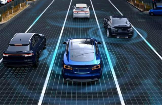
Deep Learning and Computer Vision have been insanely popular in autonomous systems and are now used everywhere. The field of Computer Vision grew intensely over the last decade, especially for obstacle detection.
Obstacle detection algorithms such as YOLO or RetinaNet provide 2D Bounding Boxes giving the obstacles’ position in an image using Bounding Boxes. Today, most object detection algorithm are based on monocular RGB cameras and cannot return the distance of each obstacle.
To return the distance of each obstacle, Engineers fuse the camera with LiDAR (Light Detection And Ranging) sensors that use laser to return depth information. Outputs from Computer Vision and LiDAR are fused using Sensor Fusion.
The problem of this approach is the use of a LiDAR, expensive. One useful trick engineers use is to align two cameras and use geometry to define the distance of each obstacle: We call that new setup a Pseudo-LiDAR.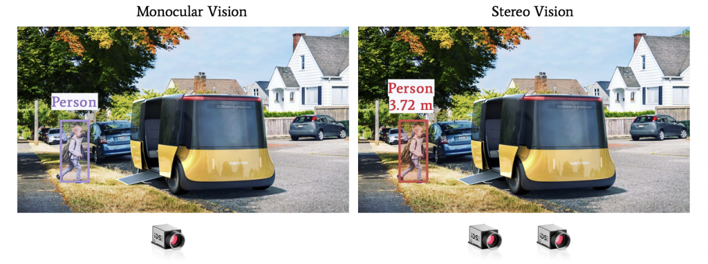
Pseudo LiDAR leverages geometry to build a depth map and combines this with object detection to get the distance in 3D.
How to achieve distance estimation using Stereo Vision?
Here’s the 5 steps pseudo-code to get the distance:
Calibrate the 2 cameras (intrinsic and extrinsic calibration)
Create an epipolar scheme
Build a disparity map and then a depth map
Then depth map will then be combined with an obstacle detection algorithm and we’ll estimate the depth of the bounding box pixels. More on that at the end of the article.
Let’s start!
1. Intrinsic and Extrinsic Calibrations
Every camera needs calibration. Calibration means converting a 3D point (in the world) with [X,Y,Z] coordinates to a 2D Pixel with [X,Y] coordinates.
Camera Models
Cameras today use the Pinhole Camera model.
The idea is to use a pinhole to let a small number of ray lights through the camera and thus get a clear image.
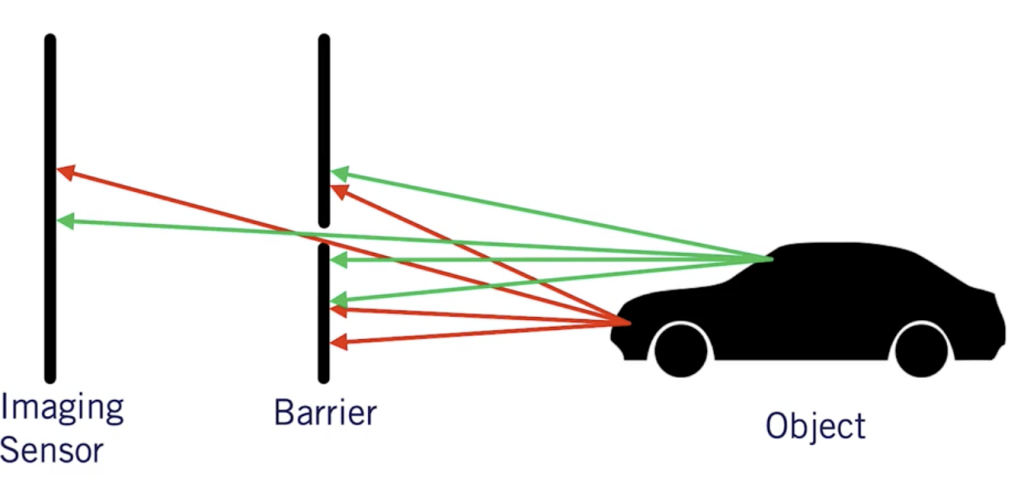
Without that barrier in the middle of the image, every ray light would pass and the image would be blurry. It also allows us to determine the focal length f used for zooming and better clarity.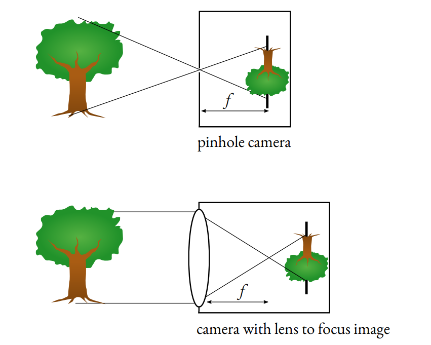
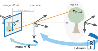
To calibrate a camera, we’ll need to apply a transformation from the world coordinates to pixel coordinates going through camera coordinates.
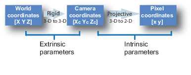
The conversion from World Coordinates to Camera Coordinates is called extrinsic calibration. The extrinsic parameters are called R (rotation matrix) and T (translation matrix).
The conversion from Camera Coordinates to Pixel Coordinates is called intrinsic calibration. It requires inner values for the camera such as focal length, optical center, …
The intrinsic parameter is a matrix we call K.
Calibration
The K matrix is found through camera calibration.
Generally, we use a checkerboard and automatic algorithms to perform it. When we do it, we tell the algorithm that a point in the checkerboard (ex: 0,0,0) corresponds to a pixel in the image (ex: 545, 343).
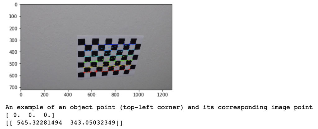
For that, we must take images of the checkerboard with the camera, and after some images and some points, a calibration algorithm will determine a calibration matrix for the camera by minimizing a least square loss.
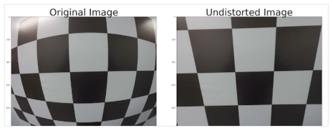
Generally, calibration is necessary to remove image distortion. Pinhole camera models include a distortion, the “GoPro Effect”. To get a rectified image, a calibration is necessary. A distortion can be radial or tangential. Calibration helps to undistort an image.
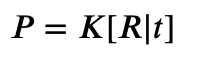
Here’s the matrix that camera calibration returns:
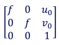
f is the focal length — (u₀,v₀) is the optical center: these are the intrinsic parameters.
Every Computer Vision Engineer must know and master camera calibration. It is the most basic and important requirement. We are used to working with images online and never touch hardware, that’s a mistake.
— Try and run OpenCV for camera calibration following this link.
Homogeneous Coordinates
In the process of camera calibration, we have two formulas to get a point O from the world to the pixel space:
World to Camera Conversion

Camera to Image Conversion
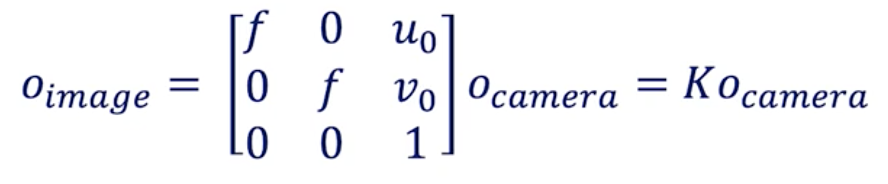
When you do the maths, you arrive at this equation:
World to Image Conversion

If you look at the matrix sizes, it doesn’t match.
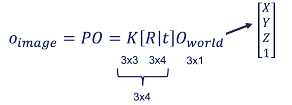
For that reason, we need to modify O_world from [X Y Z] to [X Y Z 1].
This “1” is called a homogeneous coordinate.
2. Epipolar Geometry — Stereo Vision
Stereo Vision is about finding depth based on two images.
Our eyes are similar to two cameras. Since they look at an image from different angles, they can compute the difference between the two point of view and establish a distance estimation.
Here’s an example of a stereo camera setup. You will find something similar in most self-driving cars.
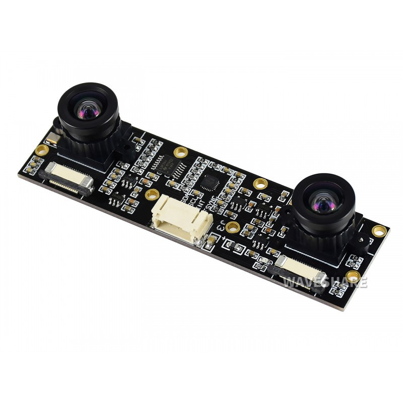
How can stereo cameras estimate depth?
Imagine you have two cameras, a left and a right one. These two cameras are aligned in the same Y and Z axis. Basically, the only difference is their X value.
Now, have a look at the following plan.
Stereo Setup
Our goal is to estimate the Z value, the distance, for the O point (representing any pixel in an image).
X is the alignment axis
Y is the height
Z is the depth
The two blue plans correspond to the image from each camera.
Now consider this in a bird-eye view.
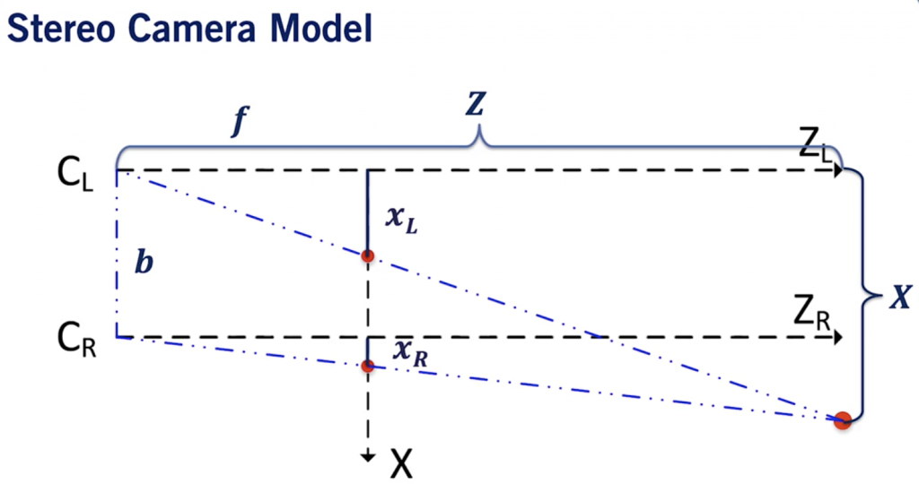
Bird Eye View of a Stereo Setup
xL corresponds the the point in the left camera image. xR is the same for the right image.
b is the baseline, it’s the distance between the two cameras.
If you do the Thales theorem, you’ll realize that we can arrive at two equations:
For the left camera:
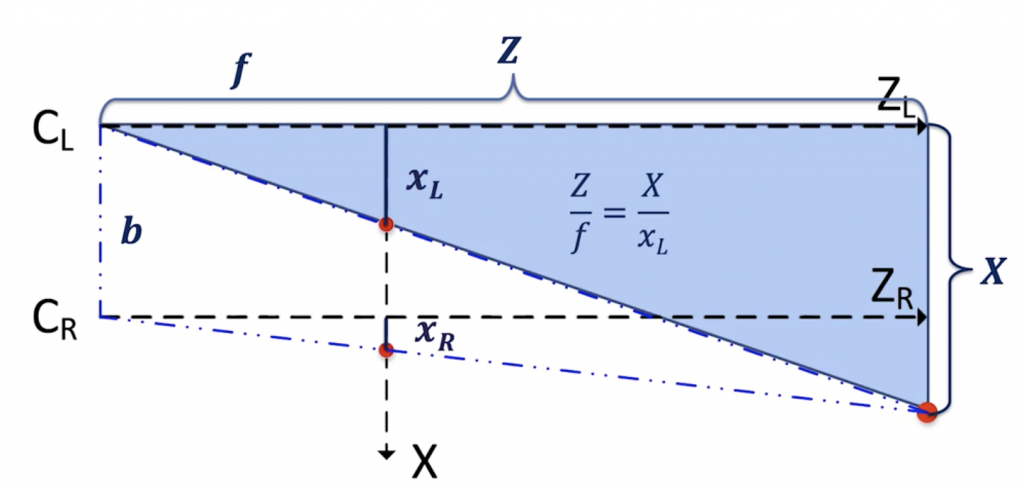
Left Camera Equations
👉 We get Z = X*f / xL.
For the right camera:
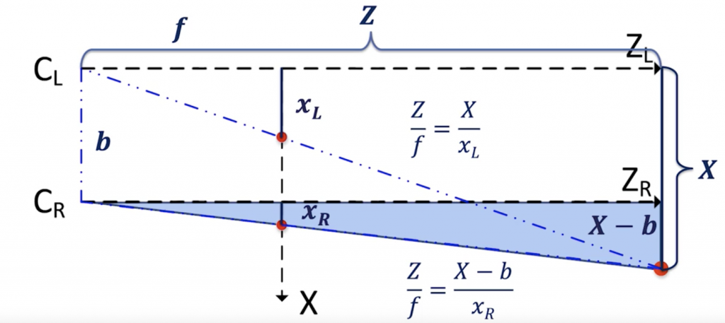
Right Camera Equations
👉 We get Z = (X — b)*f/xR.
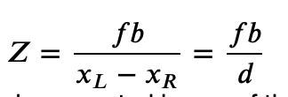
Put together, we can find the correct disparity d =xL — xR and the correct XYZ position of an object.
3. Disparity & Depth Maps
What is disparity?
Disparity is the difference in image location of the same 3D point from 2 different camera angles.
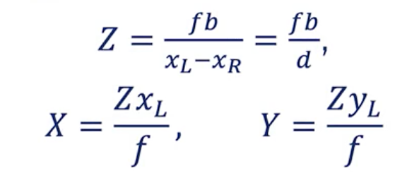
Stereo Vision Equations
👉 Thanks to stereo vision, we can estimate the depth of any object, assuming we do the correct matrix calibration.
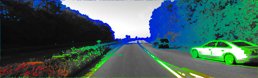
It even computes a depth map or disparity map:
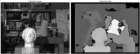
Disparity Map
Why “epipolar geometry” ?
To compute the disparity, we must find every pixel from the left image and match it to every pixel in the right image. This is called the Stereo Correspondance Problem.
To solve this problem —
Take a pixel in the left image
Now, to find this pixel in the right image, simply search it on the epipolar line. There is no need for a 2D search, the point should be located on this line and the search is narrowed to 1D.
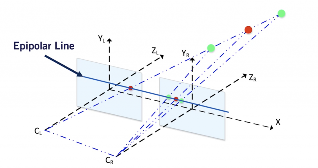
The Epipolar Line
This is because the cameras are aligned along the same axis.
Here’s how the epipolar search works:
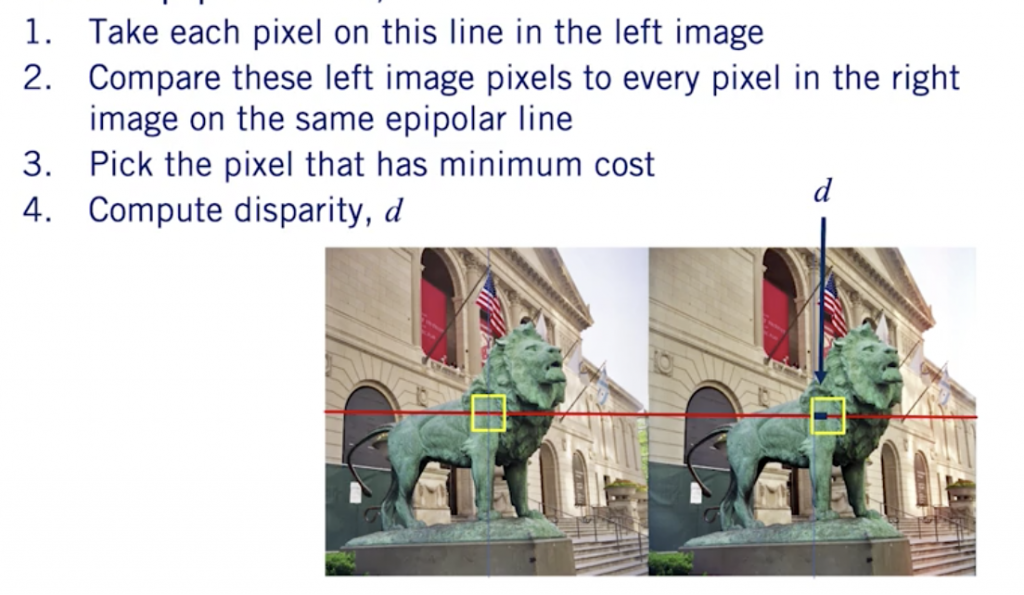
Epipolar Search
Application: Building a Pseudo-LiDAR
Now, it’s time to apply these to a real world scenario and see how we can estimate depth of an object using Stereo Vision.
Consider two images —
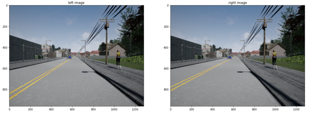
Each of these images has extrinsic parameters R and t, determined in advance by calibration (step 1).
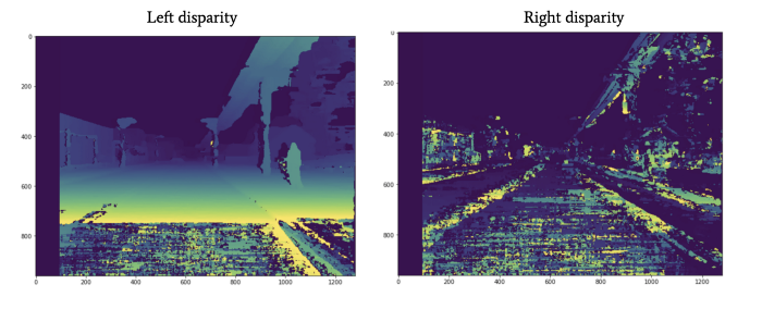
Disparities
For each image, we can compute a disparity map in respect to the other image. We will:
Determine the disparity between the two images.
Decompose the projection matrices into the camera intrinsic matrix 𝐾, and extrinsics 𝑅, 𝑡.
Estimate depth using what we’ve gathered in the two prior steps.
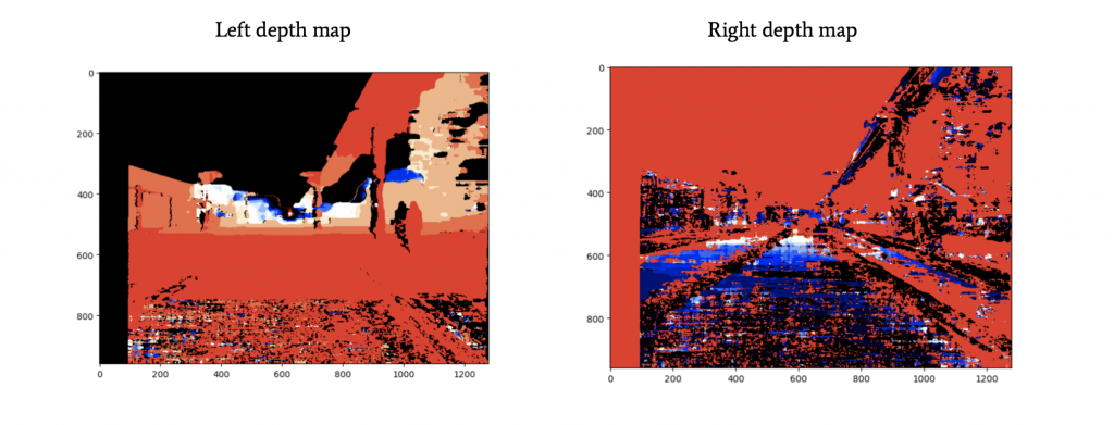
We will get the disparity maps for the left and the right images.
To help you understand better what disparity means, I have found this awesome Stack Overflow explanation:
Disparity map refers to the apparent pixel difference or motion between a pair of stereo images.
To experience this, try closing one of your eyes and then rapidly close it while opening the other. Objects that are close to you will appear to jump a significant distance while objects further away will move very little. That motion is the disparity.
In a pair of images derived from stereo cameras, you can measure the apparent motion in pixels for every point and make an intensity image out of the measurements.
From Disparity to Depth Maps
👉 We have two disparity maps, that tells us basically what is the shift in pixels between two images.
We have, for each camera, a projection matrix — P_left and P_right.
In order to estimate the depth, we’ll need to estimate K, R, and t.
An OpenCV function called cv2.decomposeProjectionMatrix() can do that and get K, R, and t from P; for each camera.
Depth Map
It is now time to generate the depth map.
The depth map will tell us the distance of each pixel in an image, using the other image and the disparity map.
The process is the following:
Get the focal length 𝑓 from the 𝐾 matrix
Compute the baseline 𝑏 using corresponding values from the translation vectors 𝑡
Compute depth map of the image using our formula from before and the calculated disparity map d:
We do that computation for each pixel.
Estimating depth of an obstacle
We have a depth map for each camera! Now, imagine we combine this with an obstacle detection algorithm such as YOLO. Such algorithm will return, for every obstacle, a bounding box with 4 numbers: [x1; y1; x2; y2]. These numbers represent the coordinates of the upper left point and the bottom right point of the box.
We can run this algorithm on the left image for example, and then use the left depth map.
Now, in that bounding box, we can take the closest point. We know it, because we know the distance of every single point of the image thanks to the depth map. The first point in the bounding box will be our distance to the obstacle.
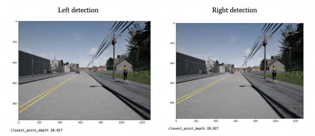
Boum! We just built a pseudo-LIDAR!
Thanks to stereo vision, we know not only the obstacles in the image, but also their distance to us! This obstacle is 28.927 meters away from us!
Stereo Vision is something that turns 2D Obstactle Detection into 3D Obstacle Detection using simple geometry and one additional camera. Today, most emerging “edge” platforms consider Stereo Vision, such as the new Open CV AI Kit or integrations on Raspberry and Nvidia Jetson cards.
In terms of costs, it stays relatively cheap compared to using a LiDAR and still offers great performances. We call that “pseudo-LiDAR” because it can replace LiDAR in its functions: Detect obstacles, classify them, and localize them in 3D.
Exercitationem molestiae tempore accusantium. Ratione impedit natus similique aut. Excepturi ex recusandae nam fugiat. Dicta est repellendus id dolorum.
Dolorem sed nihil alias consequuntur ipsa est porro quisquam. A inventore quod dolorum voluptas possimus. Eum quo eligendi libero.